Красноярск, ул. Вавилова, 1/39 (ТЦ «Атмосфера дома») ежедневно
+7 905 088 66 33
Красноярск, ул. Новосибирская, 7 (ТК «Славянский», 1 этаж) ежедневно
+7 923 771 33 23
товаров 0 | на 0 руб

Здравствуй, гость!

вход для своих | регистрация


свет светодиодная лента

Светодиодная лента RGB со встроенным контроллером на чипах LPD6803

Светодиодная лента RGB со встроенным контроллером на чипах LPD6803

ID = 1522

400 руб.

в магазине на ул. Вавилова 2 шт.
в магазине на ул. Новосибирской 0 шт.
на складе 0 шт.

добавить в корзину

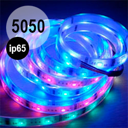
Лента сетодиодная, RGB, со встроенным контроллером на чипах LPD6803.

Лента имеет один чип-контроллер на каждые три светодиода, и позволяет зажигать каждую тройку любым цветом, независимо от других. Глубина цвета - 15 бит (5 бит на каждый цветовой канал)

Предназначена для создания систем динамического света, а также бегущих строк, световых досок, светодиодных лент и даже полноценных видео экранов.

30 диодов на метр. Исполнение IP-68 (максимальная защита, в силиконовой трубке). Питается от источника 12 вольт, максимальный ток потребления 0.6 ампера на метр.

Цена за метр
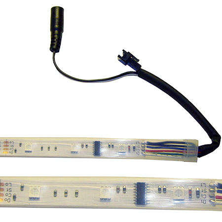
На разъём питания подаём 12 вольт. Чёрный провод с разъёма данных - на GND Arduino, красный - на digital 12, синий - на digital 11
Ниже приведён код:
 #include 

//Example to control 10 RGB LED Modules.
//Bliptronics.com
//Ben Moyes 2009
//Use this as you wish, but please give credit, or at least buy some of my LEDs!
//
// Choose which 2 pins you will use for output.
// Can be any valid output pins.
int clockPin = 12;
int dataPin = 11;

byte  SendMode=0;   // Used in interrupt 0=start,1=header,2=data,3=data done
byte  BitCount=0;   // Used in interrupt
byte  LedIndex=0;   // Used in interrupt - Which LED we are sending.
byte  BlankCounter=0;  //Used in interrupt.
unsigned int BitMask;   //Used in interrupt.

//Holds the 15 bit RGB values for each LED.
//You'll need one for each LED, we're using 10 LEDs here.
//Note you've only got limited memory on the Arduino, so you can only control 
//Several hundred LEDs on a normal arduino. Double that on a Duemilanove.

unsigned int Display[10];  

void setup() {
  byte Counter;

  pinMode(clockPin, OUTPUT);
  pinMode(dataPin, OUTPUT);

  // Turn all LEDs off.
  for(Counter=0;Counter < 10; Counter++)
    Display[Counter]=Color(Counter,0,31-Counter);
  
  show();

  Timer1.initialize(25);           // initialize timer1, 25 microseconds refresh rate.
  Timer1.attachInterrupt(LedOut);  // attaches callback() as a timer overflow interrupt

}


//Interrupt routine.
//Frequency was set in setup(). Called once for every bit of data sent
//In your code, set global Sendmode to 0 to re-send the data to the pixels
//Otherwise it will just send clocks.
void LedOut()
{
  switch(SendMode)
  {
    case 3:            //Done..just send clocks with zero data
      digitalWrite(dataPin, 0);
      digitalWrite(clockPin, HIGH);
      digitalWrite(clockPin, LOW);
      break;
    case 2:               //Sending Data
      if (BitCount==0)    //First bit is always 1
        {  digitalWrite(dataPin, 1);
            BitMask=0x8000;//Init bit mask
        }
      else if(BitMask & Display[LedIndex])  //If not the first bit 
//then output the next bits (Starting with MSB bit 15 down.)
        digitalWrite(dataPin, 1);
      else
        digitalWrite(dataPin, 0);
      
      BitMask>>=1;
      BitCount++;
      
      if(BitCount == 16)    //Last bit?
      {
        LedIndex++;        //Move to next LED
        if (LedIndex < 10) //Still more leds to go or are we done?
        {
          BitCount=0;      //Start from the fist bit of the next LED             
        }
        else
          SendMode=3;  //No more LEDs to go, we are done!
      }
      // Clock out data.
      digitalWrite(clockPin, HIGH);
      digitalWrite(clockPin, LOW);
      break;      
    case 1:            //Header
        if (BitCount < 32)              
        {
        digitalWrite(dataPin, 0);
        BitCount++;
        if(BitCount==32) 
          {
            SendMode++;      //If this was the last bit of header then move on to data.
            LedIndex=0;
            BitCount=0;
          }
        }
      digitalWrite(clockPin, HIGH);
      digitalWrite(clockPin, LOW);

      break;
    case 0:            //Start
      if(!BlankCounter)    //AS SOON AS CURRENT pwm IS DONE. BlankCounter 
      {
        BitCount=0;
        LedIndex=0;
        SendMode=1; 
      }  
      digitalWrite(clockPin, HIGH);
      digitalWrite(clockPin, LOW);

      break;   
  }
  //Keep track of where the LEDs are at in their pwm cycle. 
  BlankCounter++;
}

void show()
{
  // The interrupt routine will see this as re-send LED color data.
  SendMode = 0;
}

// Create a 15 bit color value from R,G,B
unsigned int Color(byte r, byte g, byte b)
{
  //Take the lowest 5 bits of each value and append them end to end
  return( ((unsigned int)g & 0x1F )<<10 | ((unsigned int)b & 0x1F)<<5 | (unsigned int)r & 0x1F);
}


// Show a colour bar going up from 0 to 9
void ColorUp( unsigned int ColourToUse)
{
  byte Counter;
  for(Counter=0;Counter < 10; Counter++)
  {
    Display[Counter]=ColourToUse;
    show();
    delay(25);
  }  
}

// Show a colour bar going down from 9 to 0
void ColorDown( unsigned int ColourToUse)
{
  byte Counter;

  for(Counter=10;Counter > 0; Counter--)
  {
    Display[Counter-1]=ColourToUse;
    show();
    delay(25);
  }  
}


//Input a value 0 to 127 to get a color value.
//The colours are a transition r - g -b - back to r
unsigned int Wheel(byte WheelPos)
{
  byte r,g,b;
  switch(WheelPos >> 5)
  {
    case 0:
      r=31- WheelPos % 32;   //Red down
      g=WheelPos % 32;      // Green up
      b=0;                  //blue off
      break; 
    case 1:
      g=31- WheelPos % 32;  //green down
      b=WheelPos % 32;      //blue up
      r=0;                  //red off
      break; 
    case 2:
      b=31- WheelPos % 32;  //blue down 
      r=WheelPos % 32;      //red up
      g=0;                  //green off
      break; 
  }
  return(Color(r,g,b));
}

void loop() {

  unsigned int Counter, Counter2, Counter3;
  
  // Lets show some demo patterns.
  // Just change Display array, then set SendMode to 0
  
  //Spin LED with colour changing
  for(Counter=0;Counter < 10;Counter++)
  {
    for(Counter2=0; Counter2 < 10 ; Counter2++)
    {
      Display[Counter2] = Wheel(Counter * 10 + Counter2);
      show();

      delay(25);
      Display[Counter2] = Color(0,0,0) ;     
      show();

    }
  }


  //Scrolling Rainbow Effect
  for(Counter=0; Counter < 200 ; Counter++)
  {
    Counter3=Counter * 1;
    for(Counter2=0; Counter2 < 10; Counter2++)
    {
      Display[Counter2] = Wheel(Counter3%95);  //There's only 96 colors in this pallette.
      Counter3+=10;
    }    
    show();
    delay(25);

  }


  //Color wipes.
  for(Counter=0;Counter < 2;Counter++)
  {
    ColorUp(Color(random(0,32),random(0,32),random(0,32)));
    delay(500);
    ColorDown(Color(random(0,32),random(0,32),random(0,32)));
    delay(500);
  }
}
Понадобится библиотека TimerONE.


Светодиодная лента RGB со встроенным контроллером на чипах LPD6803